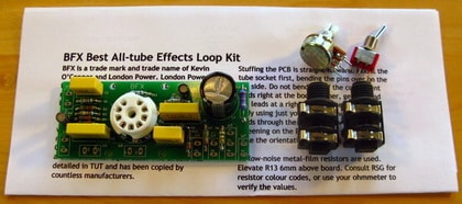
London Power’s kits allow the hobbyist or amp builder to add features to an existing project or to build a new project from scratch. Each kit contains the circuitry relevant to itself. For example, a preamplifier kit contains the circuitry that makes up the audio signal path ONLY; the kit will require a power supply to support it.
All of our kits use high-quality components, including: metal-film 1% tolerance resistors; flame-proof metal-oxide and wire-wound resistors where required; long-life electrolytic capacitors; plastic and ceramic capacitors; select semiconductors; ceramic tube sockets; industry-standard jacks and pots. The pots and jacks have PC-pins and we include small PCBs to mount them on and for the wiring to be easily attached to.
Our printed circuit boards use twice the industry standard for copper thickness to assure reliable and reworkable connections. For some kits, you can order just the PCB and notes, or also the “hard to get parts” unique to the board. For either of these variations, the pot and jack boards are not included.
Kit notes include the schematic of the kit, the board layout, installation and mounting instructions. Some kits include mounting hardware if there is a single way to mount the board. Kit notes are only available with the kit. For tutorials on how a given kit or circuit functions, refer to our books.
The product description for each kit contains dimensions for the PCB, dimensions of the assembled kit, and some information about the kit’s function. Tube-based kits DO NOT include the tubes. Tube-based kits can usually be mounted two ways and the PCBs are silk-screened on both sides of the board. A special mounting instruction note is included with these kits.
The assembler must provide wire, solder and a chassis to support the kit safely, as required or as relevant to the kit.
General Component Selection Guide
Resistors are the most common component in most linear circuits. In a tube circuit, plate resistors and supply decoupling resistors should be 5-600mW and ideally rated for the supply voltage present – yes! resistors have a voltage rating. Cathode- and grid-circuit resistors can be 0.125W or higher, most often 250mW for cost and availability. The PCB footprint for these low-wattage positions will range from 0.2″ long to 0.4″, although there may be occasion where the leads are left longer to span traces on the board.
Power resistors are metal-oxide or wire-wound and flame-proof. These will be 1W and up, rated for 500V and up.
Filter capacitors and plate coupling caps must be rated for the supply voltage present. Note that in the case of a direct-coupled cathode-follower and preceding gain-stage anode, the caps here are rated for the supply voltage present. All other capacitors are rated for the signal size they must face: EQ caps should be 100V or higher; grid-circuit caps can be 50V and up; cathode caps only see the cathode voltage, so typically 6V or more for preamp stages but 16V or higher for EL-84 and 63V or higher for 6V6 and other power tubes. Grid-circuit caps in fixed-biased amplifiers should be rated for the sum of the bias voltage plus the driver plate supply.
Note that electrolytic caps do not require derating as they are listed with WORKING VOLTAGE. Similarly, plastic film and mica caps do not require derating. Ceramic caps can be used close to their rating unless the circuit is a switch-mode type, where the cap must be rated for two to three times the voltage present to exhibit its rated capacitance at the switching frequency and its harmonics.
Diodes should be rated for the voltage of the circuit they are in. Note that a centre-tapped power transformer plate winding has an end-to-end voltage that the half-bridge diodes must fully block. For example, a 300-0-300Vac winding is 600Vac total, or about 850V peak. A 1kV diode will be marginal and is likely to fail given that the unloaded transformer voltage can be 10-20% higher. In this application, higher-rated diodes are required, or diodes wired in series for each position.
Similarly, transistors and other semiconductors can be used close to their voltage limits provided their safe-operating limits are respected, i.e. keep current and heat low. Mosfets are particularly sensitive to being over-heated despite the claims regarding their robustness.
Fuses need to be derated by 25% typically to account for self-heating and ambient effects, and to avoid nuisance fuse failures.
Wire should have a voltage rating appropriate to its position in the circuit, and its current capacity should be similarly appropriate. Hobbyists and some builders often waste money on very heavy wire where the current is exceedingly low.
TUT3 (The Ultimate Tone volume 3) expands on all of the above and details proper layout and wiring methods for lowest-noise and best note articulation. The Galactic Ground Method shown in TUT3 is universally applicable to all technologies and to all construction formats.


