Description
Q-FET, a member of London Power’s Q-system of switching kits, interfaces London Power’s Q-LATCH (or similar control circuitry) with four groups of jfet switch elements wired for series and/or shunt switching. Q-FET is the equivalent of four of our Q-SF single jfet controllers plus Q-LDV LED driver.
- four independent control groups
- four series-switching control lines
- four shunt-switching control lines
- any number of n-channel jfets per line
- function LED driver (4 LEDs)
- voice LED driver (4 LEDs)
- easy DIP-switch programming (optional – Q-DIP)
- LEDs for voice and function (optional)
- requires +/-12Vdc for series control
- requires -12Vdc for shunt control only
Q-FET creates the proper control voltage ranges for both shunt-connected jfet elements and for series-connected jfet elements.
Shunt switching uses ground-referenced switch elements. N-channel jfets wired this way require a negative control voltage, typically just -12Vdc.
Series switching uses floating switch elements. N-channel jfets wired for series switching require both positive and negative voltage, or a “split rail” supply. Q-FET accommodates both ranges when operated from +/-12Vdc. If you are only using shunt switching, then only -12Vdc is required.
An additional operating mode allows each control block to produce complementary shunt-jfet control lines. Just short C24 or replace it with a jumper, and then use the series control line as an out-of-phase shunt control line.
Each of the four control blocks within Q-FET can control series and shunt jfets simultaneously and maintain those jfets in the correct states with regard to signal muting: shunt element ‘off”, series element ‘on’. In a given system, the functions of the control blocks may not necessarily correspond to voice selections, or to channels, and may be controlled from any of the input “voice” control lines. Each block is considered to be a “function” or “feature” controller and has its own LED to show that it has activated its output. The function LEDs use current steering, so that even if all four LEDs are lit, they only draw the current of a single LED.
The incoming control lines typically correspond to “voices” of a guitar system, and there is an onboard voice LED drive circuit. This is useful when the Q-LATCH voice selector is wired in a remote location, as a foot switch, and the Q-FET provides local annunciation of the voice selected while Q-LATCH provides the same for the remote position.
Any number of jfets may be tied to any control line and the numbers per line do not have to be the same. Jfet gates can be tied directly to the shunt control lines. Use discrete jfets, each with a gate diode, for the series-connected jfets.
When used with a +/-12Vdc supply, Q-FET’s series output can be used to control grounded-source power n-channel mosfets. These are useful for switching high power loads, high voltage loads, etc., such as cathode selection of power tubes, or selection of Power Scale control pots.
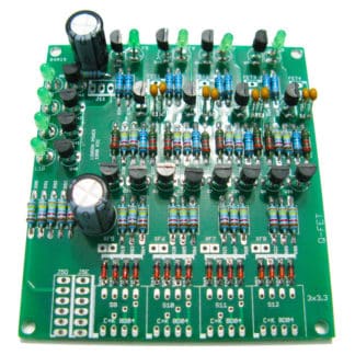
Assembly of Q-FET is quick and easy with the high-quality PCB and kit notes. The mounting holes are designed to line up with those in Q-LATCH, Q-RLY and Q-VX so that the boards can be stacked if required.
Q-FET can be fitted with high-quality DIP switches for programming, allowing easy change of the voice lines that control each function block. Add up to four Q-DIP, depending on how many of the control blocks you need for your application. If you do not require this capability, jumpers can be soldered as required to attain the functionality needed.
Note that DIP switches can always be added later, using Q-DIP or an equivalent.
Kit requires assembly.
PCB size: 3 x 3″, 76 x 76mm
See also:
Q-DIP – DIP switches for easy programming
Q-JFET must be used for series-connected jfets
For more information:
– see our page, About Our Switching Kits
– download our informative PDF: London Power Switching Kits Selection & Application (135 kB, 22 pages)